Chapter 14: What’s Next – From Research to Reality
The system described in the preceding thirteen chapters is not a whiteboard design. It runs. The occupancy grid builds a persistent spatial model from sensor data. The navigation loop calls an LLM every cycle and validates its decisions against a strict schema. The local planner finds collision-free paths through A* search. The vision pipeline converts camera frames into scene graphs. The fleet coordinator merges world models from multiple robots. There are 346 tests proving all of this works. But there is a significant distance between “works in simulation with a mock LLM” and “works on a physical robot navigating your living room.” This chapter maps that distance.
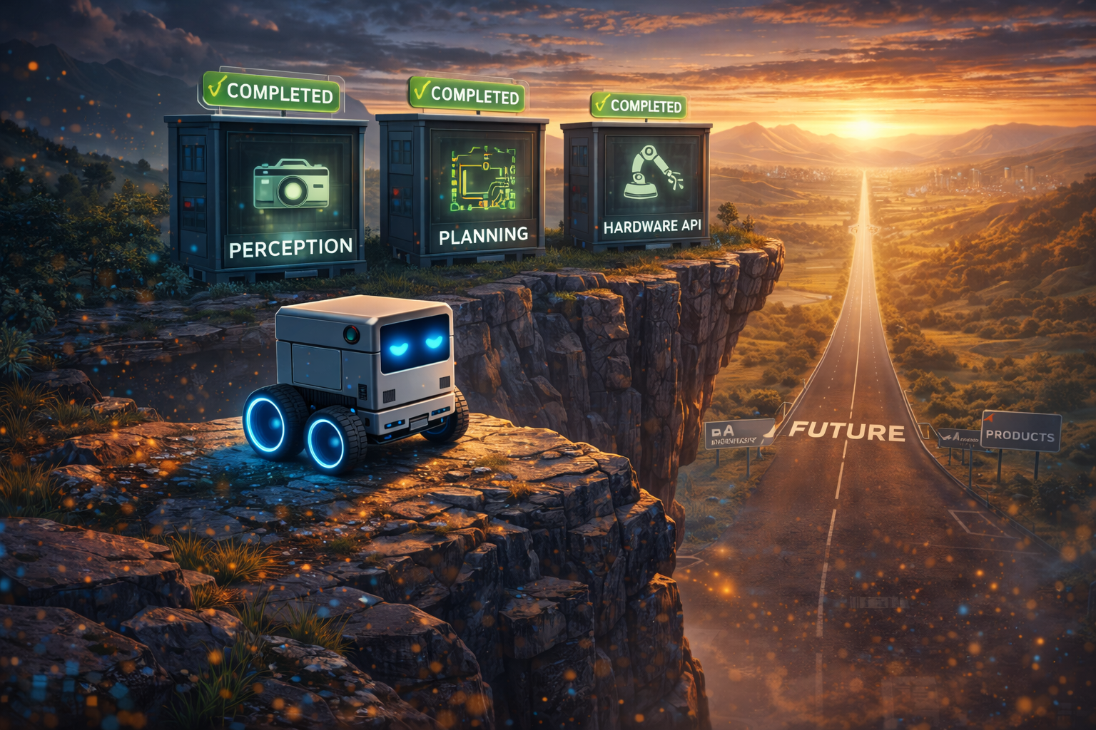
graph LR
    P0["Phase 0-2<br/>Navigation POC"] -->|DONE| V1["V1 Hardware<br/>Software Layer"]
    V1 -->|DONE| DEPLOY["Physical<br/>Deployment"]
    DEPLOY -->|NEXT| FLEET["Fleet over<br/>MQTT"]
    FLEET --> PLUGIN["Plugin<br/>Architecture"]
    PLUGIN --> NATIVE["Native Binary<br/>Generation"]

    style P0 fill:#065f46,color:#fff
    style V1 fill:#065f46,color:#fff
    style DEPLOY fill:#b45309,color:#fff
    style FLEET fill:#1e3a5f,color:#fff
    style PLUGIN fill:#1e3a5f,color:#fff
    style NATIVE fill:#4a1d96,color:#fff
Current Implementation Status
Everything described in Phases 0 through 5 of the original roadmap is implemented and tested:
| Component | Status | Test Coverage |
|---|---|---|
| World Model (50x50 occupancy grid) | Done | world-model-bridge, metrics, serializer, provider |
| LLM Navigation Loop | Done | navigation-e2e, navigation-runtime, navigation-types |
| Candidate Generator | Done | candidate-generator |
| Local Planner (A*) | Done | local-planner |
| LLM World Model Corrections | Done | llm-corrections |
| Vision Simulator | Done | vision-simulator |
| Vision Scene Bridge | Done | vision-scene-bridge |
| Vision Pipeline E2E | Done | vision-pipeline-e2e |
| Sensor Bridge | Done | sensor-bridge |
| Predictive World Model | Done | predictive-world-model |
| Fleet Coordinator | Done | fleet-coordinator |
| Navigation HAL Bridge | Done | navigation-hal-bridge |
| Navigation UI Bridge | Done | navigation-ui-bridge |
| OpenRouter Inference Adapter | Done | openrouter-inference |
The full test suite: 346+ tests across 21 suites, all passing.
The Next Milestone: V1 Stepper Cube Robot Physical Deployment
The software layer is complete. Every component – firmware, kinematics, WiFi transport, HAL bridge, navigation loop – is implemented and tested. The next milestone is physical deployment: assembling the V1 Stepper Cube Robot, flashing the firmware, validating the communication protocols, and running the LLMos navigation loop on real hardware.
The repository already dictates the exact hardware (ESP32-S3 + ESP32-CAM + 28BYJ-48
steppers + 8cm cube chassis). See Agent_Robot_Model/Readme.md for the complete BOM
and wiring diagrams. The full deployment plan is in
Chapter 15.
Phase 1: Physical Assembly and Kinematic Calibration
The LLMos math relies on precise physical measurements. If the hardware deviates from
the .stl / .blend files, the LLM will hallucinate its location in space.
- 3D print the chassis from
Agent_Robot_Model/Robot_one/(8cm cube) - Mount the rear ball caster (stepper motors have low torque; reducing friction prevents wheel slip)
- Verify wheel dimensions match the codebase: 6.0 cm wheel diameter (18.85 cm circumference), 10.0 cm wheel base
- If wheels differ, calibrate with:
{"cmd":"set_config","wheel_diameter_cm":F,"wheel_base_cm":F}
Phase 2: Communication Protocol Validation
Two parallel networks for brain and body:
- The “Eyes” (ESP32-CAM, Port 80): Flash with
firmware/esp32-cam-mjpeg/esp32-cam-mjpeg.ino. Validate: hithttp://<ESP32-CAM-IP>/streamin a browser and see 320x240 @ 10fps MJPEG. - The “Spinal Cord” (ESP32-S3, Port 4210): Flash with
firmware/esp32-s3-stepper/esp32-s3-stepper.ino. Validate: send via UDP:{"cmd":"move_cm","left_cm":10.0,"right_cm":10.0,"speed":500}– robot should move forward exactly 10cm (~2173 steps).
Phase 3: Activating the LLMos Navigation Loop
- Configure ESP32 IP addresses in the runtime environment
- Run the NavigationHALBridge with PhysicalHAL connected to the V1 robot
- The local Qwen3-VL-8B looks at
/stream, identifies open paths, and the TypeScript runtime compiles that into UDP commands - Respect max speed: 1024 steps/s (~4.71 cm/s) – exceeding this causes stepper skip
Phase 4: Closing the Loop with Spatial Memory
- Continuously poll
{"cmd":"get_status"}for step-count odometry - Stepper motors are precise – step counts provide accurate dead-reckoning
- Test: place robot facing a wall. Camera detects wall. Host LLM queries odometry.
Generates
{"cmd":"rotate_deg","degrees":90.0,"speed":1024}.
Local Qwen3-VL-8B Server
The OpenRouter adapter (lib/runtime/openrouter-inference.ts) provides cloud-based
LLM inference, but real-time robot control will benefit from local inference. The plan
is to run Qwen3-VL-8B-Instruct through llama.cpp or vLLM on the host machine’s GPU.
Target latency: under 500ms per frame for instinct decisions, under 3 seconds for
RSA-enhanced planning.
Phase 3: Swarm Intelligence (Q3 2026)
The FleetCoordinator in lib/runtime/fleet-coordinator.ts already implements
world model merging and multi-robot coordination in memory. Phase 3 takes this to
physical hardware.
MQTT Transport for ESP32 Fleet
ESP32 microcontrollers have native MQTT support through ESP-IDF. The fleet
communication protocol defines four message types: SNAPSHOT_SHARE (world model
exchange), TASK_ASSIGN (sector allocation), HEARTBEAT (liveness), and
LEADER_ELECT (coordination). The esp32-device-manager.ts in lib/hardware/
already defines the fleet configuration structure with leader-follower mode.
RSA Swarm Consensus with Real Robots
The RSA engine (lib/runtime/rsa-engine.ts) supports a swarm consensus mode where
multiple robots’ observations are aggregated through the Recursive Self-Aggregation
algorithm. Each robot contributes its local world model snapshot and camera frame.
The aggregation produces a unified world model and coordinated exploration plan.
Testing this with physical robots – three ESP32 units simultaneously mapping an
unknown room – is the milestone that validates the fleet architecture.
Multi-Robot 3D Arena Visualization
The RobotCanvas3D.tsx component currently renders a single robot. Extending it to
display multiple robots with distinct colors, their individual world models, and
communication links between them provides the visual feedback needed for fleet
development and debugging.
World Model Merging in Real-Time
The fleet coordinator’s mergeWorldModels() method uses Bayesian confidence fusion
to resolve conflicting observations. Robot A sees a cell as free with confidence 0.7.
Robot B sees it as an obstacle with confidence 0.9. The merger produces a result
weighted by confidence and recency. Doing this in real-time over MQTT, with robots
moving and observing continuously, is the engineering challenge.
Phase 4: Plugin Architecture (Q4 2026)
LLMos is built on markdown. Agents are markdown files. Skills are markdown files. The kernel rules are markdown. This makes the system naturally extensible – anyone who can write a markdown document can contribute a robot behavior.
Community Skill Marketplace
The volume system already supports three tiers: User, Team, and System. Skills start in the User volume and get promoted to Team after 5+ successful uses with 80%+ success rate, then to System after 10+ uses with 90%+ success. A public registry backed by Git would let the community share skills across installations.
Plugin Manifest Format
Third-party contributions need a standard manifest: what hardware the plugin requires, what HAL capabilities it uses, what inputs and outputs it expects. This is the contract between plugin authors and the LLMos runtime.
Third-Party Sensor Driver Plugins
The HAL’s VisionInterface and LocomotionInterface are abstract. A plugin for a
LiDAR sensor, a depth camera, or a different motor controller would implement these
interfaces and register through the plugin system. The navigation loop does not
change – it talks to the HAL, and the HAL talks to whatever hardware is plugged in.
The Neural Compiler: From JSON to Machine Code
This is the defining research direction for LLMos. Today, the LLM outputs JSON strings that the ESP32 must parse. Tomorrow, the LLM generates bytecode – 6-byte hex arrays that the ESP32 reads directly into hardware registers. Eventually, the LLM generates native Xtensa machine code that executes without any interpreter.
graph LR
    E1["Epoch 1<br/>JSON strings<br/>~15ms parse"] -->|NOW| E2["Epoch 2<br/>6-byte bytecode<br/>~0.1ms"]
    E2 -->|NEXT| E3["Epoch 3<br/>Native Xtensa<br/>~0.00001ms"]

    style E1 fill:#065f46,color:#fff
    style E2 fill:#b45309,color:#fff
    style E3 fill:#7c3aed,color:#fff
Epoch 2: The Bytecode VM
The LLMos Instruction Set Architecture (ISA) v1 defines 13 opcodes in a 6-byte frame. The same move command that takes 58 bytes of JSON becomes 6 bytes of hex:
JSON:     {"cmd":"move_cm","left_cm":10,"right_cm":10,"speed":500}  (58 bytes)
Bytecode: AA 01 64 64 CB FF                                         (6 bytes)
Grammar-constrained decoding via llama.cpp/vLLM ensures that Qwen3-VL-8B outputs only valid hex – no conversational text, no formatting drift. The firmware transition is incremental: dual-mode (JSON + bytecode), then bytecode only.
Epoch 3: Native Binary Generation
The LLM understands the Xtensa instruction set and generates raw .bin blocks that
execute via function pointers in the ESP32’s IRAM. No parser. No interpreter. The
LLM’s output is the machine code.
See Chapter 16: The Neural Compiler for the full ISA specification, grammar definitions, prompting techniques, and the firmware transition plan.
Open Research Questions
Three questions that do not yet have clear answers:
How small can the runtime LLM be? Qwen3-VL-8B works for navigation decisions, but can a 3B or 1B model handle the same task? The model-size boundary determines the minimum hardware cost for a robot that can reason about its environment. Every halving of model size roughly halves the GPU memory requirement and doubles the inference speed.
Can RSA swarm consensus scale to 10+ robots? The current fleet coordinator handles a handful of robots. At ten or more, the world model merging becomes a quadratic problem unless you introduce hierarchical aggregation – cluster leaders that merge locally before reporting to a global coordinator. The RSA algorithm supports this in theory. Whether it works in practice with real latency and packet loss is an open question.
When does the distributed VM architecture collapse to single-device? Today, the LLM runs on a host computer and sends commands to the ESP32. As edge AI chips improve, the LLM could run directly on the robot. At that point, the distributed architecture becomes unnecessary overhead. When does this crossover happen? 2027? 2030? The answer depends on how fast edge inference catches up to the model sizes that spatial reasoning requires.
Can an LLM reliably generate safe machine code? Grammar-constrained decoding ensures valid bytecode format, but native code generation requires safety guarantees – the LLM must not emit code that violates step limits, disables the emergency stop, or causes memory corruption. Formal verification of LLM-generated binaries for constrained domains (motor control) is an open research problem that sits at the intersection of AI safety and compiler verification.
Contributing
The project welcomes contributions in several areas:
- Test arenas – Design new navigation challenges in
lib/runtime/test-arenas.ts - HAL drivers – Implement
HardwareAbstractionLayerfor new hardware platforms - Sensor integrations – Connect new sensor types through the
VisionInterface - Navigation strategies – Improve the candidate generator or local planner
- Documentation – Expand the book, add diagrams, improve code comments
- Performance – Profile and optimize the navigation cycle pipeline
- Bytecode VM – ESP32-S3 firmware that accepts 6-byte hex commands
- Grammar-constrained inference – GBNF grammars for bytecode output
- Native code safety – Formal methods for LLM-generated Xtensa binaries
See CONTRIBUTING.md for setup instructions and contribution guidelines. See ROADMAP.md for the full development plan with timelines and milestone definitions.
The Vision
The trajectory of this project points toward a single idea: the gap between human intent and robot behavior should be zero.
Today, programming a robot requires learning C++, installing heavy IDEs, writing firmware, debugging serial protocols, and manually coding every behavior. The robot does not understand what it is doing. It executes compiled instructions.
Tomorrow, with LLMos: describe what you want in plain English. The development LLM creates and evolves the agents as markdown files. The runtime LLM runs them in real time on local hardware – seeing, reasoning, and acting in the physical world. Agents learn from every interaction, promote successful patterns through the volume system, and coordinate as swarms. No cloud dependency for runtime. No coding required.
The thirteen chapters before this one describe the machinery that makes this possible: occupancy grids, navigation loops, vision pipelines, fleet coordination, hardware abstraction, and a test suite that proves it all works. The V1 Stepper Cube Robot hardware layer is built – firmware, kinematics, WiFi transport, safety enforcement. What remains is the physical assembly, protocol validation, and the first time a robot navigates a room using LLMos as its brain.
The foundation is laid. The tests pass. The firmware is written. Now we build the robot – and then we teach the LLM to speak silicon’s native language.
Previous: Chapter 13 – Getting Started: Your First 10 Minutes Next: Chapter 15 – V1 Hardware Deployment: From Code to Robot See also: Chapter 16 – The Neural Compiler: From JSON to Machine Code