Chapter 7: The Nervous System – One Interface, Two Worlds
There is a moment in every robotics project where you realize that your beautifully architected software works perfectly in simulation and catastrophically on real hardware. Motors overshoot. Sensors return garbage. Serial connections drop mid-command. The gap between the simulated world and the physical one is not a crack – it is a canyon.
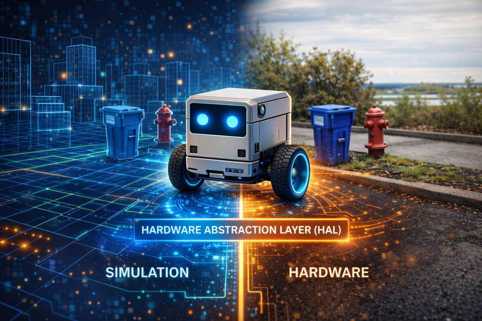
Traditional robotics deals with this by writing two separate codebases: one for testing, one for deployment. LLMos takes a different approach. It places a single interface between the LLM and all hardware, simulated or physical, and guarantees that the same high-level command produces equivalent behavior in both worlds.
graph TB
    LLM["LLM Decision<br/>'move to (2.5, 1.0)'"]
    HAL["HAL Interface<br/>lib/hal/types.ts"]

    subgraph SIM["Simulation World"]
        THREE["Three.js Physics"]
        MESH["Robot Mesh"]
    end

    subgraph PHYS["Physical World"]
        UDP["UDP JSON<br/>port 4210"]
        ESP["ESP32-S3"]
        MOT["Stepper Motors"]
    end

    LLM --> HAL
    HAL -->|"SimulationHAL"| THREE
    THREE --> MESH
    HAL -->|"PhysicalHAL"| UDP
    UDP --> ESP
    ESP --> MOT

    style LLM fill:#b45309,color:#fff
    style HAL fill:#5b21b6,color:#fff
    style SIM fill:#1e3a5f,color:#fff
    style PHYS fill:#065f46,color:#fff
The LLM says “move to (2.5, 1.0).” The HAL translates. The robot neither knows nor cares whether it exists inside a browser or on a desk.
The Design Principle
The HAL exists because of a fundamental architectural decision: the LLM should never know or care whether it is controlling a Three.js mesh in a browser or a differential drive robot on a desk. It issues commands like “move to position (2.5, 1.0, 0)” and “rotate left 90 degrees.” The HAL translates those into the correct low-level operations for the target environment. The firmware becomes a servant, not a master.
The full interface is defined in lib/hal/types.ts.
HALMode and HALToolResult
Every HAL instance operates in one of three modes:
// lib/hal/types.ts
export type HALMode = 'simulation' | 'physical' | 'hybrid';
Simulation mode routes commands to the Three.js engine. Physical mode routes them over serial, WiFi, or Bluetooth to an ESP32. Hybrid mode runs both simultaneously.
Every HAL call returns the same result structure:
// lib/hal/types.ts
export interface HALToolResult {
  success: boolean;
  data?: Record<string, unknown>;
  error?: string;
  timestamp: number;
  mode: HALMode;
  executionTime?: number;
}
The mode field tells the caller which world the command ran in. If a command succeeds
in simulation but fails in physical mode, you know the problem is hardware-specific.
The Five Subsystems
The complete HAL interface composes five subsystem interfaces plus lifecycle methods:
// lib/hal/types.ts
export interface HardwareAbstractionLayer {
  mode: HALMode;
  locomotion: LocomotionInterface;
  vision: VisionInterface;
  manipulation?: ManipulationInterface;  // optional for wheeled robots
  communication: CommunicationInterface;
  safety: SafetyInterface;
  initialize(): Promise<void>;
  cleanup(): Promise<void>;
  isReady(): boolean;
  getDeviceInfo(): { id: string; type: string; mode: HALMode; capabilities: string[] };
}
Locomotion
The most heavily used subsystem provides both low-level differential drive control and high-level movement commands:
// lib/hal/types.ts
export interface LocomotionInterface {
  drive(left: number, right: number, durationMs?: number): Promise<HALToolResult>;
  moveTo(x: number, y: number, z: number, speed?: number): Promise<HALToolResult>;
  rotate(direction: 'left' | 'right', degrees: number): Promise<HALToolResult>;
  moveForward(distanceCm: number): Promise<HALToolResult>;
  moveBackward(distanceCm: number): Promise<HALToolResult>;
  stop(): Promise<HALToolResult>;
  getPose(): Promise<{
    position: { x: number; y: number; z: number };
    rotation: { yaw: number; pitch: number; roll: number };
    velocity: { linear: number; angular: number };
  }>;
}
The drive method gives raw wheel-level control: left and right motor power from -255
to 255. The higher-level methods – moveTo, rotate, moveForward – are what the
navigation loop actually uses. The HAL translates between the two.
Vision
The vision subsystem abstracts over cameras and distance sensors. captureFrame
returns a base64-encoded image – a rendered Three.js snapshot in simulation, or a
frame from the OV2640 camera on hardware. The navigation loop feeds this to Qwen3-VL
for spatial reasoning. getDistanceSensors returns readings from front, left, and
right sensors. getIMU provides acceleration, gyroscope, and heading data.
Communication
Robots communicate state through LEDs, speaker output, and telemetry: speak(text),
setLED(r, g, b, pattern), playSound(soundId), and log(message, level).
Safety
Safety is the only subsystem with synchronous state queries. isEmergencyStopped()
returns cached local state immediately – you never want to wait for an async
round-trip to check emergency status. The getSafetyStatus() method returns battery
level, temperature, and accumulated errors.
HAL Configuration
// lib/hal/types.ts
export interface HALConfig {
  mode: HALMode;
  deviceId: string;
  connection?: {
    type: 'serial' | 'wifi' | 'bluetooth';
    port?: string;
    baudRate?: number;
    host?: string;
  };
  simulator?: unknown;
  capabilities?: string[];
}
For simulation, pass a Three.js simulator reference. For physical mode, pass connection
settings. The capabilities array declares what the device supports.
The Physical Adapter
The PhysicalHAL class in lib/hal/physical-adapter.ts implements the full HAL for
real ESP32-S3 hardware over a newline-delimited JSON protocol:
// lib/hal/physical-adapter.ts
interface ESP32Command {
  type: 'command';
  command: string;
  params: Record<string, unknown>;
  timestamp: number;
}
Each subsystem class sends commands through a shared PhysicalConnection and parses
JSON responses. For example, the locomotion rotate method serializes direction and
degrees into an ESP32 command, awaits the response with a 5-second timeout, and wraps
it in a HALToolResult. If the ESP32 does not respond, the promise rejects and the
HAL returns success: false. The LLM never hangs waiting for hardware.
// lib/hal/physical-adapter.ts (simplified)
export class PhysicalHAL implements HardwareAbstractionLayer {
  readonly mode: HALMode = 'physical';
  readonly locomotion: LocomotionInterface;
  readonly vision: VisionInterface;
  readonly communication: CommunicationInterface;
  readonly safety: SafetyInterface;

  constructor(options: { deviceId: string; connectionType: ConnectionType; ... }) {
    this.connection = new PhysicalConnection(options.connectionType, { ... });
    this.locomotion = new PhysicalLocomotion(this.connection);
    this.vision = new PhysicalVision(this.connection);
    this.communication = new PhysicalCommunication(this.connection);
    this.safety = new PhysicalSafety(this.connection);
  }
}
The Safety Stack
Safety is a four-layer gate. Every command must pass all four before wheels turn:
graph TD
    LLM["Layer 1: LLM Decision<br/>MOVE_TO (2.5, 1.0)"] -->|"Valid action?"| HAL_V["Layer 2: HAL Validation<br/>Bounds check, e-stop check"]
    HAL_V -->|"Parameters safe?"| FW["Layer 3: Firmware Safety<br/>Speed limits, step limits,<br/>host timeout"]
    FW -->|"All clear?"| MOT["Layer 4: Motor Execution<br/>Wheels turn"]

    HAL_V -->|"VETO"| FAIL["HALToolResult<br/>success: false"]
    FW -->|"VETO"| ESTOP["Emergency Stop"]

    style LLM fill:#b45309,color:#fff
    style FW fill:#065f46,color:#fff
    style FAIL fill:#991b1b,color:#fff
    style ESTOP fill:#991b1b,color:#fff
If any layer vetoes, the result propagates up as HALToolResult with success: false.
The LLM receives this on the next cycle and reasons about what went wrong.
The Navigation HAL Bridge
The file lib/runtime/navigation-hal-bridge.ts connects the NavigationLoop to the HAL.
Each cycle follows four steps: capture a camera frame, run the LLM navigation cycle,
execute the decision on the HAL, and report the result back to the loop.
The decision execution translates action types to HAL calls:
// lib/runtime/navigation-hal-bridge.ts (simplified)
switch (decision.action.type) {
  case 'MOVE_TO':
  case 'EXPLORE': {
    if (path?.success && path.waypoints.length > 0) {
      const wp = path.waypoints[Math.min(1, path.waypoints.length - 1)];
      await this.hal.locomotion.moveTo(wp.x, wp.y, 0);
    } else {
      await this.hal.locomotion.moveForward(10); // nudge recovery
    }
    break;
  }
  case 'ROTATE_TO': {
    const yaw = decision.action.yaw_deg ?? 90;
    await this.hal.locomotion.rotate(yaw >= 0 ? 'right' : 'left', Math.abs(yaw));
    break;
  }
  case 'STOP':
  default:
    await this.hal.locomotion.stop();
}
MOVE_TO and EXPLORE follow the A*-planned path. If no path exists, the bridge nudges
forward 10cm as recovery. The run method loops until the goal is reached or stopped.
The ESP32 Device Manager
For multi-robot scenarios, ESP32DeviceManager in
lib/hardware/esp32-device-manager.ts manages a fleet with device registration,
firmware deployment, telemetry collection, and three fleet coordination modes:
// lib/hardware/esp32-device-manager.ts
export interface FleetConfig {
  syncMode: 'independent' | 'synchronized' | 'leader-follower';
  leaderDeviceId?: string;
  defaultMap: string;
  defaultGame: string;
  autoStart: boolean;
}
Each device gets its own HAL instance via createDeviceHAL(), which routes to
simulation or physical mode based on device type.
Hardware Target: Robot V1 – Stepper Cube Robot
The reference hardware platform is the Robot V1 – Stepper Cube Robot, an 8cm 3D-printed cube designed to tightly mount all components:
| Component | Specification |
|---|---|
| Motor Controller | ESP32-S3-DevKitC-1 (GPIO4-7, GPIO15-18 for ULN2003) |
| Camera | ESP32-CAM (AI-Thinker), OV2640, MJPEG streaming |
| Motors | 2x 28BYJ-48 stepper (5V unipolar, 4096 steps/rev, 64:1 gear ratio) |
| Drivers | 2x ULN2003 Darlington arrays |
| Wheels | 6cm diameter, 10cm wheel base |
| Support | Rear ball caster (low friction for stepper torque) |
| Power | 5V 2A USB-C |
| Chassis | 8cm 3D-printed cube from Agent_Robot_Model/Robot_one/ |
The full bill of materials, wiring diagrams, and assembly instructions are in
Agent_Robot_Model/Readme.md.
Stepper Kinematics
The file lib/hal/stepper-kinematics.ts encodes the precise math for the 28BYJ-48
stepper motors. Every distance and rotation command flows through these conversions:
| Parameter | Value |
|---|---|
| Steps per revolution | 4096 (with 64:1 gear ratio) |
| Wheel circumference | 18.85 cm (pi x 6cm) |
| Steps per cm | ~217.3 |
| Max speed | 1024 steps/s (~4.71 cm/s) |
| Max acceleration | 512 steps/s^2 |
Key conversion functions:
// lib/hal/stepper-kinematics.ts

distanceToSteps(cm)        // 217.3 steps per cm
rotationToSteps(degrees)   // differential drive arc calculation
velocityToStepsPerSecond(cmPerSec)
calculateArcSpeeds(radiusCm, speedCmS)  // inner/outer wheel speeds
calculateMoveDuration()    // trapezoidal motion profile
The rotationToSteps function computes the arc length each wheel must travel for an
in-place rotation. For a 90-degree turn with a 10cm wheel base, each wheel travels
pi * 10 / 4 = 7.85 cm in opposite directions, which is 7.85 * 217.3 = 1706 steps.
If the calibrated wheel dimensions differ from the codebase defaults, the
set_config command updates the firmware constants.
WiFi Transport
The V1 robot communicates over WiFi using two separate protocols on two separate
ESP32 chips. The file lib/hal/wifi-connection.ts implements the motor control
transport.
Motor Commands (ESP32-S3, UDP, Port 4210)
UDP is used instead of TCP because it has zero handshake latency, which is required for the 200ms instinct loop. The WiFi connection class provides:
- Sequence-based request-response matching
- Timeout: 2000ms with max 3 retries
- Continuous round-trip time tracking
- Statistics: commands sent, responses received, timeouts, retries
Camera Stream (ESP32-CAM, HTTP, Port 80)
The camera serves standard HTTP MJPEG:
GET /stream– multipart/x-mixed-replace JPEG frames at 320x240 @ 10fpsGET /status– JSON status (FPS, frames served, uptime, WiFi RSSI)
The host PC’s VLM (Qwen3-VL-8B) reads frames from this endpoint to generate VisionFrames for the navigation loop.
Communication Protocol
The ESP32-S3 firmware (firmware/esp32-s3-stepper/esp32-s3-stepper.ino) accepts
UDP JSON commands on port 4210:
{"cmd":"move_steps","left":N,"right":N,"speed":N}
{"cmd":"move_cm","left_cm":F,"right_cm":F,"speed":F}
{"cmd":"rotate_deg","degrees":F,"speed":F}
{"cmd":"stop"}
{"cmd":"get_status"}
{"cmd":"set_config","wheel_diameter_cm":F,"wheel_base_cm":F}
The get_status response returns the current pose (x, y, heading), accumulated
step counts for each motor, whether the motors are currently running, and the
uptime. The host uses these step counts for dead-reckoning pose updates:
deltaLeft = currentLeftSteps - prevLeftSteps
deltaRight = currentRightSteps - prevRightSteps
linearCm = (leftDistCm + rightDistCm) / 2
angularRad = (rightDistCm - leftDistCm) / wheelBase
Because stepper motors execute precise discrete steps (unlike DC motors which can slip), the odometry is highly accurate – accurate enough for the navigation loop’s world model to remain consistent over many cycles.
Firmware Safety
The file lib/hal/firmware-safety-config.ts defines the safety parameters that
the firmware enforces independently of the host:
Stepper Safety (V1 hardware):
| Parameter | Default | Range |
|---|---|---|
| Max steps/second | 1024 | 1-2048 |
| Max continuous steps | 40960 (10 revolutions) | per command |
| Host heartbeat timeout | 5000ms | 500-10000ms |
| Max coil current | 240mA | 0-300mA |
Emergency Stop Triggers:
- Host timeout (no command received for 2+ seconds)
- Step limit exceeded in single command
- Firmware watchdog timer
The firmware disables motor coils when idle to save power and prevent overheating. When the host connection drops, the robot stops immediately rather than continuing on its last command.
Serial Protocol
For wired connections, lib/hal/serial-protocol.ts provides a reliable framing
protocol with:
- Monotonic sequence numbers for request-response matching
- CRC-16/CCITT-FALSE checksums on the payload
- Ack timeout (2000ms default) with retry (3 attempts)
- Statistics tracking: frames sent, acks received, checksum errors, timeouts
This protocol is used for development and debugging. For deployment, the WiFi UDP transport is preferred because it eliminates the physical tether.
Chapter Summary
The HAL is the seam between the LLM’s abstract reasoning and the physical world. Five
subsystems provide a complete interface. The PhysicalHAL adapter translates HAL calls
into UDP JSON commands over WiFi. The V1 Stepper Cube Robot uses two ESP32 chips: one
for motor control (UDP port 4210) and one for camera streaming (HTTP port 80). The
stepper kinematics library converts distance and rotation commands to precise step
counts. The firmware enforces safety independently: host timeout triggers emergency stop,
step limits prevent runaway commands, and motor coils disable when idle. The four-layer
safety stack ensures no single failure produces dangerous behavior. The key insight: the
LLM says “move to (2.5, 1.0)” and the HAL translates – whether to Three.js physics or
to UDP packets driving real stepper motors.
Previous: Chapter 6 – Seeing the World: Camera to Grid Next: Chapter 8 – Agents, Skills, and the Markdown OS